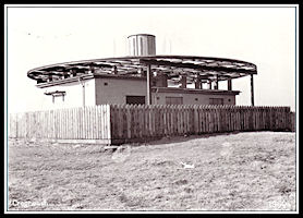
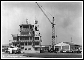
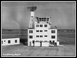
The New Control Room at Ronaldsway
The 1960s began with
all Air Traffic Control functions operational from the new control room,
installed
on the top of the former
Royal Navy watch office and giving an uninterrupted view in all directions.
|
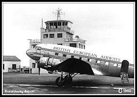
New Control Room
1960
The new Control Room
built on top of the RN Watch Office. BEA Dakota G-AGJZ parked on the apron
between the terminal and control tower.
|
With the change to using
VHF radio telephony and with cathode ray direction finding available, many
of the former support functions required by the old Medium Frequency ATC
were no longer required and the radio/direction finder operators and ATC
clerks had disappeared. The new control room was deigned to accommodate
three operational staff: The Aerodrome (or Tower) controller, the Approach
Controller and the ATC Assistant. The controllers shared a desk facing
south over the airfield with the assistant having one behind and at right
angles.
|
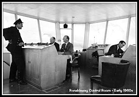
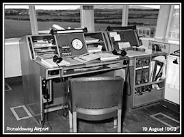
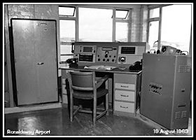
Control Room Interior
The controller's desk
is to the right, aerodrome lighting controls to the rear and assistant's
desk on the left. Controller is Joe Kearney and ATC Assistants Walter Collister
and Dougie Clucas.
|
|
|
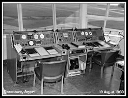
Control Desk
The two controllers
sat side by side, with the Approach Controller on the left and Tower Controller
on the right. In quieter periods Approach and Tower were probably 'bandboxed'
onto the Approach desk.
|
The Tower controller
was responsible for all aircraft and vehicle movements on the airfield
surface and for aircraft flying within the vicinity of the airport. The
Approach Controller was responsible for clearing aircraft into the Control
Zone and providing separation between Instrument Flight Rules (IFR) aircraft.
Control was entirely by procedural methods, using vertical distance or
time separation between aircraft. The only aid the Approach controller
had to assist him in his task was a VHF CRT Direction Finder. The old ex
Navy FV5 D/F was replaced in the early 1960s by a more modern Marconi AD210
unit. This was fitted with all the radio frequencies in use and could be
switched from one to another at the push of a button. When an aircraft
transmitted a message, the CRT display would emit a click and a bright
blue line trace from the centre to the edge, where the bearing could be
read off against a compass rose. Apart from the controller being able to
pass bearings to aircraft and provide Direction Finder based approaches,
the D/F was very valuable in building up a mental picture of the approximate
position of aircraft under control.
|
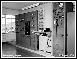
Approach Controller's
Desk
Weather reports clipped
on the left, the main panel has a clock, controls and display for AD210
D/F, wind
dials with radio controls
below. Flight progress strips on the sloping section of the desk in three
reversible bays.
|
|
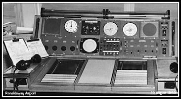
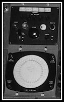
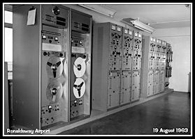
Marconi AD210 VHF
CRT D/F
Control panel and frequency
selectors at top, with the cathode ray tube display below. The D/F trace
only displayed (with an audible 'click') while an aircraft was actually
transmitting and vanished as soon as the transmission ceased.
|
|
If several IFR
aircraft arrived at the same time the first could make an approach with
'no delay' and subsequent aircraft would be held overhead the airfield,
vertically separated using the Ronaldsway M/F Non Directional Beacon (NDB)
for lateral guidance. Each aircraft would make its approach in turn and
as levels in the hold were reported vacated the aircraft above would be
descended. 'Expected Approach Times' (EATs) were issued to any delayed
aircraft to enable pilots to ensure they had enough fuel in reserve. Outbound
aircraft had to be integrated by keeping inbounds above them in the hold
until lateral separation could be proved. All instructions and clearances
were recorded on the Flight Progress Strips, which had been prepared in
advance by the ATC assistant based on Flight Plans submitted locally or
received by teleprinter.
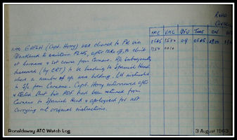
An example of the problems
facing a procedural approach controller can be found in the watch log from
3rd August 1963. Dan Air Bristol Wayfarer G-APLH had been cleared to depart
IFR for Prestwick, climbing to maintain Flight Level 45. The routing specified
was to Carnane NDB (south of Douglas) to climb overhead that beacon to
FL45 before setting course to Blackhead (Mull of Galloway, Scotland). By
the use of the D/F the controller discovered the aircraft was in fact heading
towards Spanish Head to the west of the airport 'where a number of aircraft
were holding' The captain was instructed to set course for Carnane and
when later interviewed stated that his Automatic Direction Finder (ADF)
had been 're-tuned from Carnane to Spanish Head' and apologized. Presumably
he hadn't bothered to listen to the Morse identification transmitted by
the beacons!
|
ATC Logbook 3rd August
1963
Entry detailing the
navigation error in G-APLH that was only discovered by use of the D/F
|
|
The same aircraft and
captain feature in the watch log the following day: G-APLH landed at 14:10
after an 'unorthodox' procedure onto runway 27. At 13:54 G-LH checked the
IOM beacon with the coast in sight and was cleared for direct visual approach
for runway 09. At 14:10 the pilot stated that he was downwind for runway
27 but did not have the airfield in sight. After being given QDMs (D/F
bearings to the airfield) G-LH landed on runway 27. Another inbound aircraft,
British United Airways G-YV (Dakota G-AMYV) had to be held at Carnane for
twelve minutes until the Dan Air aircraft had eventually landed. Such were
the delays and ATC problems with procedural approaches where you can't
'see' where the aircraft is. In the first example the D/F probably averted
a serious incident if not accident.
Air Traffic Control
Assistant Duties
The ATC assistant was
now the sole 'support staff' for the controllers and had various duties
assigned. Outside duties would include inspecting the airfield runways
and taxiways before the station opened in the morning, as required during
the watch and again before dark if night time flying was to take place.
Most of the assistants duties were inside the tower however. Flight Plans
and other ATC signals would be received by teleprinter, located on the
ground floor of the tower. The Teleprinter Operator would tear the printed
copy off the machine and dispatch it to the tower assistant via the Lamson
Tube system. Similarly any outgoing signals, Flight Plans, Departure Messages
etc. would be hand written by the assistant and sent 'downstairs' via the
tube. The assistant hand wrote the Flight Progress Strips before passing
over to the appropriate controller. After the flight had landed or for
outbounds had been transferred to another agency, the assistant would record
the details in the Aircraft Movement logbook and file the strip. Another
Lamson tube routed to the Met Office and the Met Observer would hand write
half hourly Met Observations on the appropriate form and dispatch to ATC
upstairs.
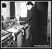
|
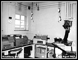
Air Traffic Control
Assistant Desk - 1963
Equipped with telephones,
Movement log book and blank Flight Progress Strips. The Lamson Tubes are
positioned right of the chair.
|
Pilots or company representatives
would file Flight Plans with the assistant who, after checking them and
correcting
any inaccuracies would
add the Aeronautical Fixed Telecommunications Network (AFTN) teleprinter
addresses for other relevant ATC units and dispatch them to 'teleprinters'
via the Lamson Tube. The Teleprinter section shared a room on the ground
floor with the airport switchboard.
 AFTN Teleprinter
Section
AFTN Teleprinter
Section
|
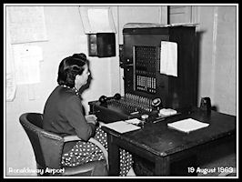 The Airport Telephone
Switchboard
The Airport Telephone
Switchboard
|
Ronaldsway Meteorological
Office
The 'Met Office' was
located on the first floor of the control tower and was staffed by a Met
Forecaster and a Met Observer. The observer would make half hourly routine
observations, recording them in a ledger and then sending a copy to ATC
and another to Teleprinters, both by the Lamson Tube System. If conditions
changed rapidly, 'special' observations would be made as required - if
storms were passing by the observer could be very busy! The Met Forecaster
prepared forecasts on a regular basis, disseminated as the observations
to ATC via the 'tube' and the rest of the world by the AFTN teleprinter
network. The forecaster also offered a personal briefing to ATC staff and
to pilots who would all pop into 'Met' before taking up their duties.
|
|
|
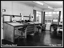 Met Forecaster's
Desk
Met Forecaster's
Desk
|
 Met Observer's Desk
|
1960s Navigation Aids
As mentioned before,
the VHF D/F could be used to provide either a pilot interpreted 'D/F letdown'
or a controller interpreted 'QGH' approach, the aim being to enable a pilot
to descend through cloud until visual with the airport when he could make
a 'circling' approach to land on the most suitable runway. With the 'GJE'
Non Directional Beacon (NDB) at Ronaldsway approaches would have been published
for the main 'instrument runway' of 27/09, aligning the aircraft more closely
with the runway and having a lower permissible descent height do to the
higher accuracy of the aid. The most accurate approach was using the Instrument
Landing System installed on runway 27. Once the Glidepath element had come
into use in June 1960 with the commissioning of the Santon Head Outer Marker
beacon, instrument descents could be made to around 200 ft, with the pilot
being assured that when he broke out of cloud the runway would appear directly
ahead (wind drift permitting!).
|
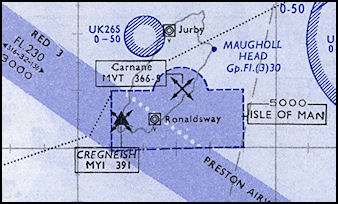
Section of 1960 Airways
Chart
From the start of the
decade, showing NDBs 'MYI' at Cregneash and 'MVT' at Carnane. The Isle
of Man Control Zone has changed from circular to rectangular with a small
enlargement to include the NDB at Carnane.
(Click map for larger
area)
|
With the adoption of
the VHF Omni directional Range (VOR) as the UK primary en-route navigation
aid a VOR at Cregneash, coding 'MYI', the same as the NDB, was 'on test'
by July 1961 with a frequency 113.9 MHz. The advantage of VOR over the
previous Radio Ranges and Non Directional Beacons was that any course required
could be selected, the Radio Range only offered four pre-determined courses.
By 1963 both the VOR
and NDB at Cregneash had been re-coded to 'IOM' and there is a watch log
entry for 7th June regarding a procedure that: 'Cambrian Airways are using
for a VOR approach to runway 09' - they were reminded that this was unofficial!
 The 'IOM' VOR beacon
at Cregneash
The 'IOM' VOR beacon
at Cregneash
|
 Working on the VOR
electronics
Working on the VOR
electronics
|
 VOR cabinets on right,
NDB on the left?
VOR cabinets on right,
NDB on the left?
|
|
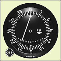
VOR Course Deviation
Indicator (CDI)
The basic aircraft instrument
associated with the VOR. Pilot selected the required track to or from the
VOR using the OBS knob, needle swings to left or right, when on the selected
track the needle is centred. TO/FROM indicator to show direction of the
VOR on course selected.
|
|
The VOR was supplemented
in due course with UHF Distance Measuring Equipment (DME) giving the same
VOR/DME capability that is still installed (albeit updated) there in 2012.
In the same period the Ronaldsway NDB was re-coded to 'RON'
|
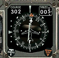
Horizontal Situation
Indicator
Later type of display
for VOR/DME or ILS. The compass rose rotated automatically to show
aircraft heading, course (and heading for autopilot) selected with knobs,
the bar indicated displacement from selected Radial/LLZ with pointer
to the left for ILS glidepath. DME distance displayed to top right of instrument.
|
Ronaldsway Radio Frequencies
At the start of the
decade Ronaldsway Approach was using 125.0 Mhz with Tower on 118.7 Mhz.
The Tower frequency changed to 123.7 on the 29th February 1960 and on 16th
January 1964 both frequencies were changed, Approach to 120.85 and Tower
to 118.9. At 15:00 on the same day, the Station Telecommunications Officer,
Mr Hewitson, advised that Approach was reverting to 125.0 due to
interference from Manchester Zone on 120.8. By the 11th February the problem
had apparently been resolved and Approach went back to 120.85, both of
these frequencies being used until 2014.
A full list of relevant
radio and navigation aid frequencies for the area near the start of the
decade. (Aerad) flight guide supplement dated April 1961:
|
Radio Telephony
Ronaldsway Approach
125.0 with 121.5 (emergency) available
Ronaldsway Tower 123.7
with 121.5 available
VHF Direction Finder
(VDF) 125.0 & 121.5
Met broadcast from Preston
on 125.5
Jurby Tower 123.7
Navigation Aids
Ronaldsway NDB 'GJE'
322 KHz. Range 10nm
Instrument Landing System
(ILS) on runway 27 'GJE' 110.1 MHz
ILS Outer Marker 75
MHz (at 2nm and offset 4,500 ft to north.
ILS Inner Marker
75 MHz
Carnane NDB 'MVT' 366.5
KHz. Range 25nm
Cregneash NDB 'MYI'
391 KHz. Range 70nm
Jurby NDB 'MWJ' 358
KHz. Range 15nm
Area Control
Preston Airways 125.1
for airway RED 3 NW of Wallasey.
(Preston also had 125.5
(FIS) 124.2 and 125.9 (Airways)
|
Radio and naviagation
aids list at the end of the decade (Aerad flight guide supplement dated
Arpil 1969)
|
Radio Telephony
Ronaldsway Approach
120.85
Ronaldsway Tower 118.9
VHF Direction Finder
(VDF) 120.85 & 118.9
Met broadcast from Preston
126.6
Jurby Tower 118.9
Navigation Aids
Ronaldsway NDB 'RON'
322 KHz. Range 10nm
Instrument Landing System
(ILS) on runway 27 110.1 MHz
ILS Inner Marker 75
MHz (No mention of an ILS Outer Marker)
Carnane NDB 'CAR' 366.5
KHz. Range 25nm
Spanish Head NDB 'IOM'
391 KHz. Range 50nm
Spanish Head VOR 112.2
MHz
Jurby NDB 'JY' 358 KHz.
Range 15nm
Area Control
Preston Airways 125.1
for Red 3 and Delta Green 27 NW of Wallasey.
(also 126.85 for FIS,
125.9, 127.45, 128.05 for other airways)
Preston Radar
125.1 (and the other airways frequencies)
|
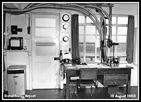
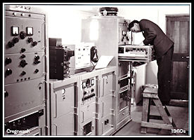
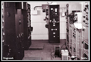
The former Control Room
on the second floor of the control tower was converted into a telecommunications
equipment
room, with radios and
tape recorders, with the old 'MCA Radio Room' towards the rear of the building
also still in use.
 The Duty 'Tels' Engineer's
Desk
The Duty 'Tels' Engineer's
Desk
|
 The former 'MCA Radio
Room'
The former 'MCA Radio
Room'
|
 New equipment in
the former Control Room
New equipment in
the former Control Room
|
The Former RN Watch Office
The original RN 'Watch
Office' unused for control purposes since the wartime years remained unoccupied
in the early 1960s although from a 1963 photograph it looks like it might
have been used as an office, possibly for flight planning by aircrews?
The desk looks like the original control desk used in the 1940s & 50s.
By 1966 the room had eventually found a use in ATC at Ronaldsway to house
the new Approach Radar section which was to remain here until the move
to the new control tower in 2010.
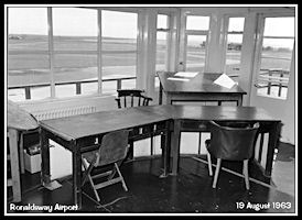 The old control desk
in the 1940s RN Watch Office
The old control desk
in the 1940s RN Watch Office
|
Radar for civil Area Control
- 1950s into 1960s
When first opened in
the 1950s, Area Control at all of the UK ATC Centres, including Preston,
had been entirely procedural, using vertical and horizontal (usually time
interval) separations based on pilot reports. The first civil Area radar
was installed at London Heathrow in 1950 to assist the controllers at Uxbridge
Centre and improve safety and expedite traffic around the various London
Airports. Radar systems installed were two American AN/CPS-1 sets
for longer range, a Marconi S232 50cm set with a range of 70 nm and a Type
13 Height Finder set. The Marconi S232 radar had a wide horizontal
beamwidth of 4 degrees, which resulted in very wide aircraft return 'blips'
at range! As mentioned in the 1950s section, the S232 radar was developed
into the S264 with a 2.5 degree horizontal beamwidth by means of a new
larger aerial and rotation equipment.
 Radars at the SATCC
on Heathrow Airport (Flight Global picture)
Radars at the SATCC
on Heathrow Airport (Flight Global picture)
|
 AN/CPS-1 radar at
Heathrow (Flight Global picture)
AN/CPS-1 radar at
Heathrow (Flight Global picture)
|
 Marconi S232 radar
|
Also installed at Heathrow
in the 1950s and a precursor of things to come at other airfields, was
a Cossor ACR -6 airfield control radar and a Decca 'Airfield Surface Movement
Indicator (ASMI), a revolutionary millimetric radar system that rotated
at 70 RPM and could track aircraft and vehicles on the ground.
 Cossor ACR-6 in an
early installation (Flight Global picture)
Cossor ACR-6 in an
early installation (Flight Global picture)
|
 Heathrow ASMI radar
display
Heathrow ASMI radar
display
|
The initial London Air
Traffic Control unit had been set up at RAF Uxbridge whereas the radars
were located on the north side of Heathrow Airport. This obviously
created some difficulties with co-ordination between the Procedural and
the Radar controllers. There was also limited space available for
the civil controllers at Uxbridge so in 1955 they had moved in with the
radar controllers at the Heathrow site which became the new Southern Air
Traffic Control Centre. There were six initial 'Sectors', two of
which dealt with traffic inbound or overflying the London Control Zone,
one with traffic departing London and the other three with en-route traffic
over the southern part of the UK. By careful use of lighting, the
procedural controllers who needed a brighter illumination to see their
Flight Progress Strips and the radar controllers who needed a darker environment
to see their radar displays, could work together in the same room, although
not actually alongside each other.
Pictures by Flight Global.
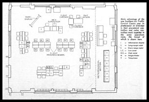 SATCC Ops Room Layout
('Flight' diagram)
SATCC Ops Room Layout
('Flight' diagram)
|
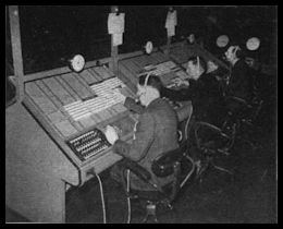 SATCC Procedural
Controllers
SATCC Procedural
Controllers
|
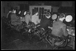 SATCC Radar Controllers
|
From the early 1960s
onwards, the first experimental area control radars were being replaced
by an updated Marconi S264A which had new electronics and a greater range.
Eventually ten were ordered and the remotely sited ones covering southern
England at Ash, Kent and Ventnor (Isle of Wight) were relayed to Heathrow
by broadband microwave links. The Southern ATCC continued in operation
until the new London Air Traffic Control Centre opened at West Drayton
in 1971. Further radars for southern England were installed at Burrington
in Devon and Clee Hill in Shropshire, plus the four longer range ones at
Heathrow. Two shorter range 10 Cm radars (Marconi ACR6 and Plessey
AR-1) were installed at Heathrow for Approach Control, who also had the
use of the longer range S264As.
Hack Green (Mersey Radar/Northern
Radar)
In north-west England,
an existing RAF Air Defence radar station was brought into use to assist
the air traffic controllers at Preston Centre, located at Hack Green in
Cheshire on the site of a wartime Ground Control of Interception (GCI)
site. Staffed by both civil and military controllers and using the callsign
'Mersey Radar' it initially used the wartime Type 7 as a surveillance radar
supplemented by Type 13 height finders, Two Type 14 (probably) radars
were added, one optimized for higher and one for lower coverage.
The unit name was changed at some point to 'Northern Radar' which
ensured commonality with the other Joint Air Traffic Control Radar Units
(JATCRUs) being established around the UK. When more modern Marconi
S264 50cm radar became available one was installed at Hack Green, moving
later to Sopley (Southern Radar) and then Aberdeen after the closure of
Hack Green. SSR radar was also installed here in the 1960s.
When the Type 82 air defence radars designed to provide target acquisition
data for the Bloodhound ground to air missile system became available for
ATC use, the one installed at RAF Lindholme near Doncaster took over both
the ATC task and Northern Radar callsign and Hack Green was closed as an
ATC site. It was subsequently used as a potential nuclear war Regional
Government Headquarters before being abandoned in the early 1990s.
It is now open as the 'Hack Green Secret
Nuclear Bunker' museum and a Marconi S264 radar aerial has been installed
in the grounds.
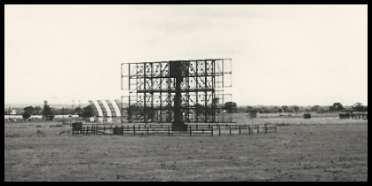 Hack Green Type 7
& S264 Radars (picture via GATCO)
Hack Green Type 7
& S264 Radars (picture via GATCO)
|
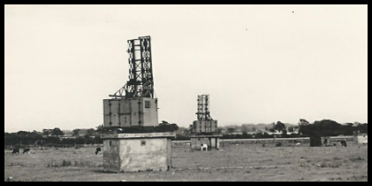 Hack Green Type 13
Height finder radars (picture via GATCO)
Hack Green Type 13
Height finder radars (picture via GATCO)
|
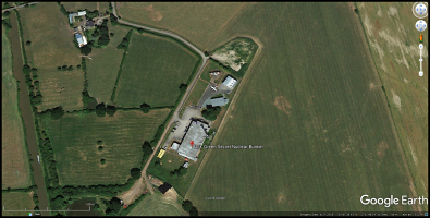 Google Earth view
of the Hack Green site in 2018
Google Earth view
of the Hack Green site in 2018
|
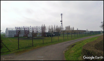 Google Streetview
picture of the Hack Green Museum site.
Google Streetview
picture of the Hack Green Museum site.
|
Antrobus Radar (at RNAS Stretton
airfield)
To assist both military
and civil traffic operating around the Manchester area a joint civil/military
radar unit was established at the Royal Navy Airfield at Stretton, in Cheshire.
Known as Antrobus (after a nearby village) this provided early radar coverage
of the Manchester area but with the radars used having a maximum range
of 60 miles, unfortunately the coverage didn't reach as far as the Isle
of Man.
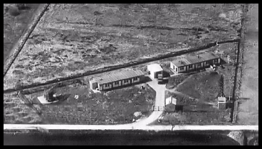 Antrobus Radar Station
|
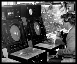 Antrobus Radar operating
position (Leslie Tranter via GATCO)
Antrobus Radar operating
position (Leslie Tranter via GATCO)
|
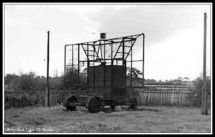 Antrobus Type 15
Radar Aerial
Antrobus Type 15
Radar Aerial
|
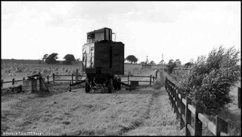 Antrobus Type 277
Radar Aerial
Antrobus Type 277
Radar Aerial
|
St Anne's Radar & Preston
ATC Radar Unit (PATCRU)
It wasn't until about
1963 that a Marconi S264A 50cm radar was installed at St Anne's, as part
of a new civil ATC project to provide radar coverage of the UK airways
system and presumably took over from Antrobus site, although the Hack Green
site (Northern Radar) seems to have continued in operation until the 1960s.
The Preston ATC Radar Unit (PATCRU) was established in the control tower
at Manchester Airport, although the procedural controllers remained at
Barton Hall, Preston. The new area radars were still 'Primary' only, so
aircraft had to be identified by the radar controller either by a report
over a notified 'Reporting Point' or by ascertaining the aircraft heading
and instructing a turn of 30 degrees or more and observing the turn on
radar. The controller then had to remember which 'blip' was which aircraft!
There was a potential future development on the horizon though, the Air
Traffic Control Radar Beacon System (ATCRBS), a development of the wartime
Identification Friend of Foe (IFF), in 1961 it was on trial at London Heathrow
airport for the Southern Air Traffic Control centre. Suitably equipped
aircraft were allocated a 'Squawk' code which produced an enhanced 'blip'
on the controllers radar screen. This was the forerunner of today's Secondary
Surveillance Radar (SSR).
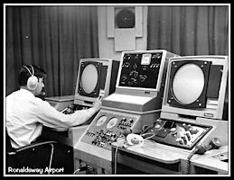
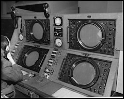 Radar at Manchester
Early radar displays
as used at PATCRU,
AD210 D/F installed
between the control positions to assist controllers identify aircraft on
radar.
(Picture via GATCO)
Radar at Manchester
Early radar displays
as used at PATCRU,
AD210 D/F installed
between the control positions to assist controllers identify aircraft on
radar.
(Picture via GATCO)
|
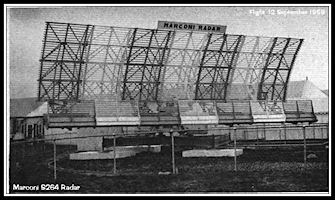 Marconi S264 Radar
at the 1958 Farnborough Air Show
Marconi S264 Radar
at the 1958 Farnborough Air Show
|
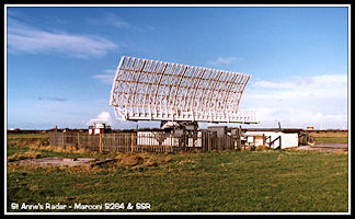 The St Anne's S264A
Radar
The St Anne's S264A
Radar
|
The St Anne's radar
would have given good coverage out to the Isle of Man and beyond, but although
obviously of great assistance to the controllers at Preston, there probably
wasn't much change in ATC procedures at Ronaldsway until radar was installed
here. There was also a 10cm Type 80 Air Defence radar installed at Bishops
Court in Northern Ireland in the late 1950s that was used for high level
ATC by Ulster Radar, a Joint Air Traffic Control Radar Unit (JATCRU), It
would have given excellent coverage over the Isle of Man, but was not available
at Preston centre.
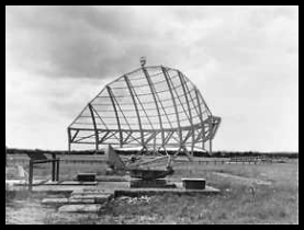
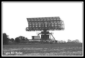 The huge Type 80
radar scanner (This one was at Sopley)
The huge Type 80
radar scanner (This one was at Sopley)
|
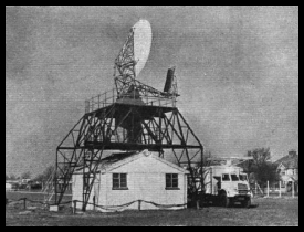
1966 - Radar installed at Ronaldsway
(Again!)
By around 1965 the IOM
Airports Board had decided to install radar at Ronaldsway. A popular airport
radar at the time was the Plessey 424, a 3 cm radar, good for 'Surveillance
Radar Approaches' but with severe limitations for vectoring and not approved
for separating aircraft due to a very narrow vertical beamwidth. It was
also prone to suffer from weather induced 'clutter'. Although considerably
more expensive, it was decided to order a Plessey AR-1 10cm radar as installed
at London Heathrow and Guernsey Airports. The radar scanner was installed
on a mast above the control tower and the 1940s RN Watch Office converted
into an Approach and Radar room.
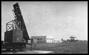
 Constructing the
new Radar mast
Constructing the
new Radar mast
|
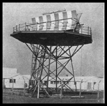
 The new Radar Scanner
in position
The new Radar Scanner
in position
|
The Approach controller
moved down from the Visual Control room, leaving just the Tower controller
and assistant there.
Two radar displays were
installed in a purpose made desk with, to the right, another desk housing
the Approach controller and assistant,
 Plessey AR-1 Radar
displays on test - 1966
Plessey AR-1 Radar
displays on test - 1966
|
 Wiring the Approach
desk, Radar to the left
Wiring the Approach
desk, Radar to the left
|
Inbound aircraft could
be now sequenced with radar and separated laterally from outbound aircraft,
cutting the inevitable delays when aircraft are controlled 'procedurally'.
Surveillance Radar Approaches could also be provided, heading instructions
being passed to keep the aircraft positioned on the extended runway centreline
with advisory heights passed every mile, it being up to the pilot to adjust
his descent rate to match.
There were no electronic
'video maps' to show airspace boundaries on the radar, perspex overlays
being employed to show the final approach tracks and distances from touchdown.
The radar display had to be manually aligned with these using radar reflectors
positioned around the airfield. When the radar was out of service for any
reason, control reverted to procedural. The Approach Controller sitting
next to radar was still in charge and would speak to inbound aircraft on
first contact, passing the latest weather and runway in use. Aircraft would
initially be separated vertically or horizontally. The Approach controller
would than hand control of the aircraft to radar, who usually operated
on the same radio frequency. For Surveillance Radar Approaches a discrete
VHF frequency could be used as the SRA required quite a lot of time critical
transmissions and other aircraft calling could block the frequency.
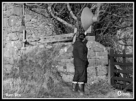
|
AR-1 Radar Reflector
At the 'Barn Site'
|
|
Aircraft had to be radar
identified by a position report from the pilot or by observing the reported
heading for a period of time and giving a turn of 30 degrees or more and
observing the turn onto the new track. The D/F was of major assistance
here, given a radar display with maybe four or five 'possible' blips all
heading in the same direction, a D/F bearing would usually indicate the
most likely culprit! Departing aircraft could be identified by observing
them appearing on the radar after the airborne time had been passed from
Tower. If there was a conflict on the airway, inbound aircraft could be
given a 'Radar Release' to Ronaldsway by Preston Radar identifying the
aircraft in conflict to Ronaldsway by reference to a common place marked
on both radar displays.
With the introduction
of radar at Ronaldsway, a new radio frequency was also allocated, 118.2
MHz. The purpose of this was to allow a radar controller to carry out a
Surveillance Radar Approach (SRA) on a discrete frequency. Providing an
SRA can take up a lot of radio time and the controller's transmissions
are time critical, so it was useful to have a quiet frequency for the purpose,
so that a range check or critical heading correction isn't interrupted
by a 'first call' on the approach frequency by a pilot who feels the need
to pass his entire flight plan details on the first transmission. With
two radar displays available, the second display could be used by another
controller (if one was available!) to split the radar functions, Radar
One carrying out initial vectoring using shared frequency 120.85 with Approach,
Radar Two providing SRAs on 118.2.
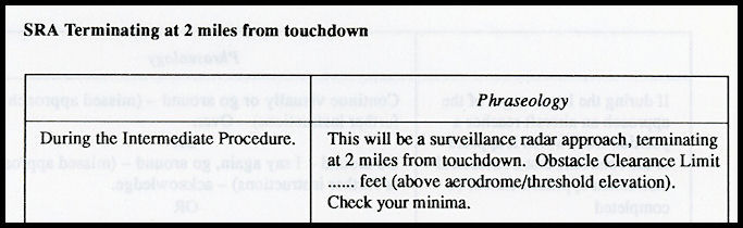
Surveillance Radar Approaches
The AR1 radar was approved
for providing Surveillance Radar Approaches (SRAs) to 2 miles from the
runway. Before the approach began the controller would read out 'the spiel'
- 'This will be a surveillance radar approach terminating at 2 miles from
touchdown. Obstacle Clearance Limit is 650 ft, check your Minima'.
The controller would then vector the aircraft to a closing heading for
the Final Approach Track and descend it to the minimum initial altitude
as shown on the Radar Vectoring Area chart, at Ronaldsway usually 1,600
ft. At 8 miles from touchdown the radar controller would press the 'request'
button on the Landing Clearance Indicator System (LCIS). This activated
a buzzer and light in Tower where the controller had a choice of three
reply buttons 'Land', 'Continue' or 'Overshoot'. Routinely the 'Continue'
button would be pressed at this stage and the appropriate light illuminate
in radar. The pilot would be requested to report when he had the
runway or lights in sight as the SRA could normally be discontinued at
this point. As the aircraft approached the runway extended centreline small
heading changes would be given by radar, usually of 5 or 10 degrees, to
keep the aircraft tracking the final approach track and the pilot requested
to 'Check Wheels'. At 5.5 miles from touchdown the pilot would be instructed
to commence descent to maintain a 3 degree glideslope. Every mile from
touchdown an advisory height would be passed and the pilot would adjust
his descent rate appropriately. Radar continued with heading changes as
needed and at 4 miles from touchdown would press 'Request' on the LCIS
again, hopefully obtaining a 'Land' light from the Tower controller, whereupon
the pilot would be cleared to land. At three miles from touchdown the advisory
height would be passed together with 'Check Decision Height'. At two miles
any final heading correction needed would be passed together with the advisory
height and 'Approach completed'. If the pilot did not have the runway in
sight an overshoot would be commenced with climb to a height as instructed
by the controller.
Initial phraseology
for SRA - click for more
|
Special Rules Zone
Zone
In the late 1960s the
Isle of Man controlled airspace was upgraded to include a Special Rules
Zone. Initially the SRZ was a smaller dimension that the Control Zone,
having a dimension of 5nm around the airport and up to 2000ft. Previously
a pilot flying under Visual Flight Rules could enter the control zone without
permission from ATC, but the addition of the SRZ meant that any pilot had
to contact Ronaldsway by radio, preferably at least 10 minutes before ETA
at the SRZ boundary and obtain permission to enter the zone. Whilst within
the zone he had to maintain two way radio contact with ATC and obey any
instructions issued. Aircraft not fitted with radio could still enter the
zone but had to telephone ATC in advance and comply with any restrictions
imposed. Eventually the SRZ was expanded to have the same dimensions as
the Control Zone, giving ATC total control over their airspace.
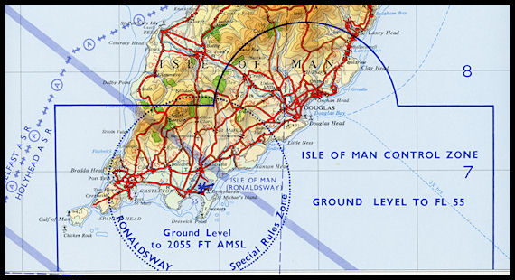 Isle of Man Control
Zone & Ronaldsway Special Rules Zone - 1968
Isle of Man Control
Zone & Ronaldsway Special Rules Zone - 1968
|
ATC
in the 1970s
|